 US Dollars
Air Management Install
The compressor, tank, valves, and gauges that turn your Airkewld air-ride bags into an actual on-demand suspension system. Push a toggle. Settle to lay-frame. Drive home at highway height. American-assembled, manual valves, archaic by design — works for decades, no firmware updates.
"No guesswork, no compromise. Our Air Ride Kits include every part for a perfect install, giving you full control over stance and comfort at the push of a button."
Archaic by Design. Reliable for Decades.
An air-ride suspension is only as good as the system that controls it. Skip the air management and you've got fancy bags with nothing telling them what to do.
Our kit gives you a 2-gallon tank, a compressor that auto-fills at 165 PSI and shuts off at 200, and manual toggle valves with gauges. Push a toggle, the bag inflates. Push the other way, it deflates. Tank refills itself in the background. That's it. No microcontroller, no calibration, no firmware.
Manual valves. American assembled. Decades of service. No app required.
Available as a 2-valve kit (one toggle per axle) or a 4-valve kit (one toggle per corner — the right answer for full air ride). Read the next section before you decide.
2 Valve or 4 Valve?
This is the call that determines what your air ride actually feels like. Get it right up front.
One toggle per axle. Front bags rise/fall together. Rear bags rise/fall together. Good for single-axle air-ride installs (just the rear, just the front), or for builders working a tight budget.
The Tradeoff
When you go around a corner, air transfers from one side of the axle to the other. The car leans like grandma's old Lincoln Continental. If you can live with that — or you're only doing one axle — this is your kit.
- Rear-only or front-only air ride installs
- Budget-focused builds
- Show cars that don't go around many corners
One toggle per corner. Each wheel inflates and deflates independently. Drive into a corner, the outside corner stays planted while the inside corner doesn't unload. Acts like a pneumatic sway bar.
The Why
If you're putting your VW on full air front-and-back, you want the 4-valve. The car drives like it's still got springs — corners flat, no Lincoln-Continental wallow, no air transferring between sides under load.
- Full air-ride builds (front + rear on air)
- Daily drivers and weekend cruisers
- Anyone who actually corners the car
- ~95% of our customers
The Numbers You Need Before You Drill
Cycle
165 – 200 PSIAuto-fill from compressor
Wiring
12V OnlyBLK = GND · RED thick = 12V
Seal
Teflon TapeAll NPT threaded joints
Tube
Square CutPush-to-click · pull-test every joint
Works on Any Classic VW — If It's 12V
The compressor needs 12 volts to spin. The pressure switch is rated for 12V circuits. The accessory loads add up. 6-volt systems will not power this kit — period.
If you're still on a 6-volt charging system, you'll need to swap to 12V before this AMK can run. You're already going to need 12V anyway for a stereo, modern lighting, or any electric fuel pump — this is the right time to make that change. Works with all classic VW models — Type 1, Type 2, Type 3, Ghia, Thing, Fridolin — as long as it's 12V.
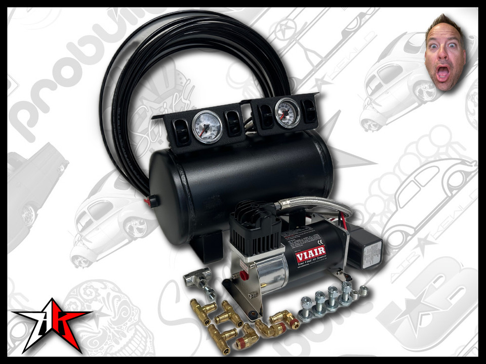
Everything to Manage the Air
Below is the 4-valve kit contents. The 2-valve kit is identical except for one valve assembly instead of two.
- Compressor — air supply, 12V
- Pressure Switch — 165 PSI ON / 200 PSI OFF, ±5%, 40A rated
- 2 Gallon Tank — 14.5″ long × 7″ diameter, 4× 1/4″ NPT ports
- Manual Valves with Gauges — (1) for 2-valve kit, (2) for 4-valve kit
- 1/4″ Air Line — tank-to-valves and valves-to-bags
- Hardware Pack — Teflon tape, fittings, bolts, washers, nylocs
- Printed Instructions (this guide)
Tank, Valves, Pressure Switch — The Numbers
Use these dimensions to plan your mount locations BEFORE you start cutting. Measure twice. Especially the tank.
2 Gallon Tank · Mount Dimensions
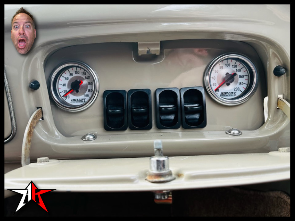
Manual Valve Assembly · Footprint
Footprint: approx. 10″ wide × 3″ tall. Each assembly has two toggle valves and a center liquid-filled PSI gauge.
2-valve kit: one assembly. 4-valve kit: two assemblies (you can mount them stacked, side-by-side, or split between glove box and dash).
Each toggle has 3 line-out ports: one feed (compressed air in) + two corner outputs (bag/shock). Read Phase 4 for the plumbing pattern.
Pressure Switch · Wiring (VIAIR 90118)
⚠ Wires should not be swapped
→ Power source (constant 12V)
→ Trigger / switch positive (IGN keyed hot)
→ Compressor positive
→ Ground
How The Air Lines Run
Four corners — two air bags up front, two air-sleeve shocks in the rear — each fed by its own toggle valve. The compressor lead line hooks into a steel female tee: one port gets the pressure switch, the other gets a 90° fitting that becomes the feed line. The feed line is your main artery — it runs up to the tank, and you tee into it anywhere you need to feed a valve.
Plan your tee locations before you cut a single line. Mock the system on the floor first — compressor on the frame head, valves in the glove box, tank under the rear seat — then walk the feed-line path through the tunnel and pick your tee points where they're easy to reach later. Soapy-water leak test every joint before you button anything up.
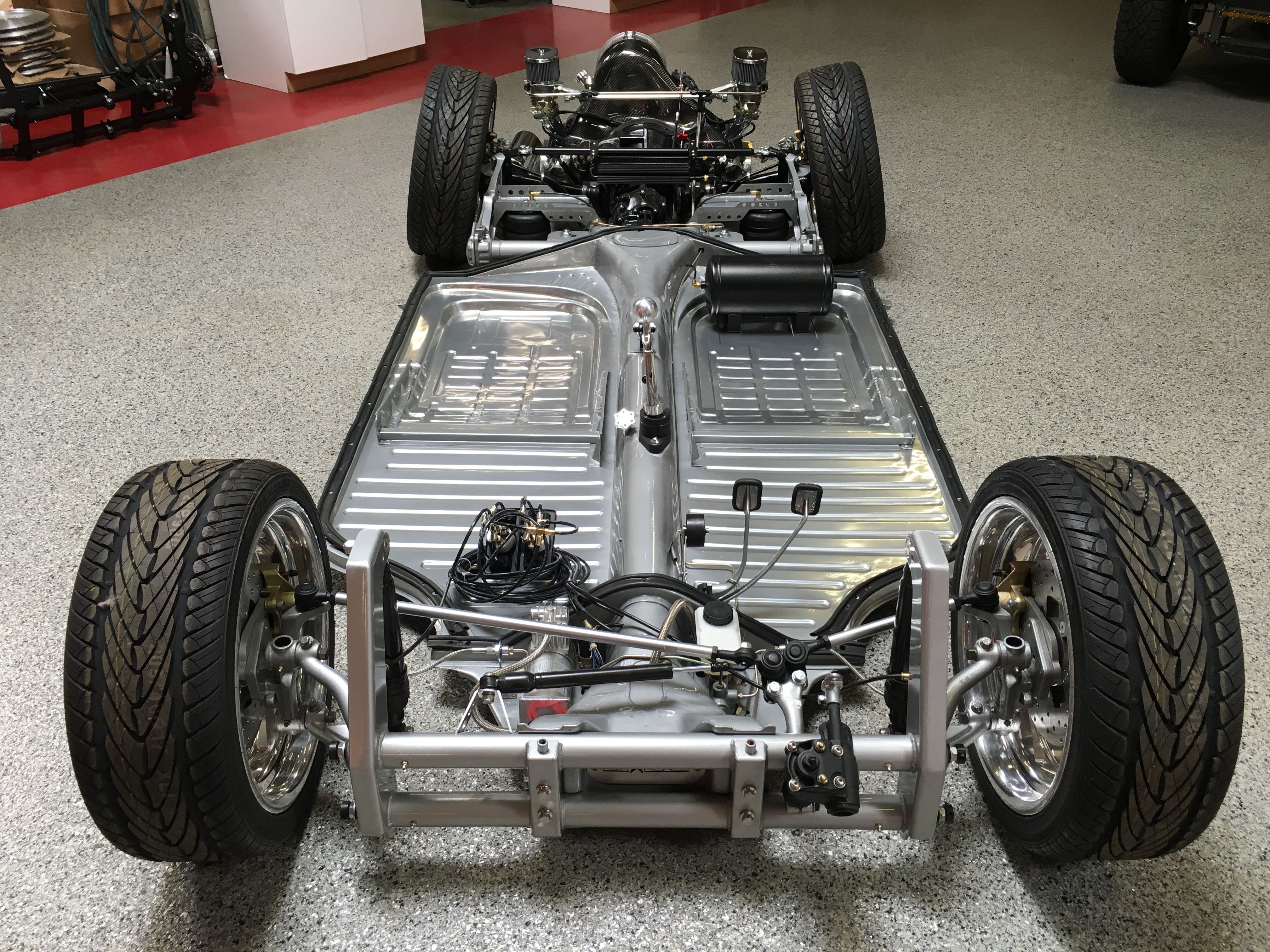
Where the Components Want to Live
These are the popular locations — not rules. Your build, your call. Here's what works clean.
Compressor
Frame head, opposite side of the master cylinder.
Gets outside cooling air. Any noise it makes is outside the cabin, not in the trunk or under the seat. Hidden from sight.
Tank
Under the rear seat, opposite side of the battery.
Balances weight. Hidden under upholstery. On some chassis you may need to trim a heater tube to clear the tank — worth the effort.
Valves & Gauges
Glove box or under the dash.
Gauges visible at a glance. Toggles in easy reach. Some builders custom-fab a center-stack panel — that works too. None of these are rules.
Filming the Dedicated AMK Series
A chassis-build video that walks through the AM install in context exists already — the dedicated AMK-only series is being filmed now.
Subscribe to Airkewld on YouTube for the alert when it goes live.
The Top 5 Install Mistakes — And How to Avoid Them
Improper Wiring
Mis-routed constant vs. keyed hot will burn the compressor. Verify before you power up. Big red = constant 12V, little red = keyed/IGN, white = compressor positive, black = ground.
Skipping the Leak Test
Soap-and-water every joint at full pressure before declaring the install done. A pinhole leak today is a flat tank tomorrow.
Tubing Not Cut Square
Angled cuts will not seal in push-to-connect fittings. Use a sharp blade or tube cutter. The square cut is what engages the internal barb.
No Thread Sealant on NPT Fittings
Teflon tape every threaded joint. The pre-applied locker on the pressure switch is the only exception — everything else needs tape on the male threads.
Air Lines Near Moving Parts
Route away from steering, pedals, and shifter linkage; rear-tunnel run is preferred. Chafe-through is silent and slow.
Tools Required · Shop the Build
No welder needed for this one. Just basic shop tools, a drill, and patience for the leak test.

Jack & Jack Stands
For getting under the chassis to drill tunnel pass-throughs and route lines.
Shop on Amazon
Drill + Bits (incl. 1/4″)
For mounting the compressor and tank, drilling tunnel pass-throughs for air lines.
Shop on Amazon

Wire Cutters / Crimpers
For trimming and crimping the four pressure-switch wires (red, white, black, plus IGN trigger).
Shop on Amazon
Sharp Razor / Tube Cutter
Square cuts only. Push-to-connect fittings won't seal on an angled cut.
Shop on Amazon
Teflon Tape + Soapy Water
Tape every NPT joint. Soapy water in a spray bottle for the leak test at the end.
Shop on AmazonAirkewld is a participant in the Amazon Services LLC Associates Program. As an Amazon Associate, we earn from qualifying purchases — at no additional cost to you.
Step by Step · The Way We'd Run It
Read each phase. The wiring matters — the leak test matters more.

Compressor
- Position compressor on chosen wing — mark and drill mount holes.
- Remove red rubber plug; install supplied air filter on intake.
- Mount with supplied hardware; leave one bolt loose for the ground.
- Land BLK ground under that bolt; tighten. Trim wire for clean run.
- Drill 1/4″ tunnel pass-through near compressor; deburr the hole.
On Type 2, mount in the engine compartment LHS near the wheel-well vent. On Beetle / Ghia, mount on the chassis Napoleon hat opposite the master cylinder — still gets cooling air, hidden from sight.
Pressure Switch
- Apply Teflon tape to the pressure switch threads; thread into the center port of the 1/4″ steel tee.
- Install 90° push-to-connect fitting in the right port of the tee (no tape — pre-locked from factory).
- Land compressor hose into the left tee port. Snug, do not gorilla-tighten.
- Wire: WHT → compressor RED · thick RED → constant 12V · thin RED → IGN · BLK → ground. (Refer to the wiring diagram above.)


Air Tank
- Mark tank position; drill four mounting holes through the chassis floor.
- Plug all unused tank ports with Teflon-taped plugs before mounting.
- Bolt tank down with supplied hardware. Drill 1/4″ feed-line pass-through; deburr.
- Land compressor → tank line; route through tunnel to keep the bay clean.
Mount the tank under the rear seat opposite the battery. On some chassis you may need to trim a heater tube to clear it — worth the effort for a hidden, balanced install.
Valves (2 or 4)
- Mount in glove box, dash, or custom enclosure — keep it CLEAN.
- Each valve has 3 line-out ports: one feed (compressed) + two corner (bag/shock).
- On 4-valve setups, tee the feed line to serve both valve bodies.
- Confirm gauge ports route to bag/shock side, not feed side.


Air Lines
- Run the main feed (tank → valves) inside the chassis tunnel for a clean look.
- Cut every line SQUARE. Push fully into the fitting until you hear the click.
- Pull-test EVERY connection — engages the internal barb and seals the joint.
- Tee off the feed line to serve each valve; route corner lines to bags/shocks.
Common myth: lines passing through drilled holes will rub through and leak. Not true. Tunnel steel is thick, the line never moves, and the tubing is too thick to puncture. Grommets are not required at tunnel pass-throughs.
Leak Test & Final Setup
- Pressurize the system. Confirm the compressor cycles between 165 and 200 PSI.
- Spray every joint with soapy water — foaming = leak. Re-seat or re-tape and retest.
- Lift the vehicle to maximum height; watch each gauge for slow pressure loss.
- Secure all lines with Adel clamps or zip-ties; verify nothing contacts moving parts.

Why We Don't Recommend Electronic AMK
Electronic air management with ride-height sensors looks cool on paper. In practice, after years of warranty calls, our take is:
- Sensors are finicky. Misalignment, dirt, vibration, temperature swings — they drift.
- The vehicle has to cycle for the sensors to work accurately. If you're in gear or the e-brake is on, the vehicle won't lift to the height you want.
- Firmware updates introduce new behaviors. Yesterday's perfect setup is today's troubleshooting call.
- When something goes wrong, you're not fixing it on the side of the road. You're calling support.
Manual air management is archaic by design. Toggle valves, mechanical pressure switch, gauge feedback. No microprocessor. No app. No firmware updates. No support tickets.
It functions perfectly for decades without maintenance.
A dedicated article on this topic is coming — we have 4 or 5 pages of warranty-call experiences to share. Subscribe to the newsletter or check the Learn library for when it lands.
"4-valve was the right call. Lays flat at shows, drives flat through corners. No Lincoln Continental wallow."
— Posted by Sal Rivera"Compressor on the frame head, tank under the seat, gauges in the glove box. Clean install. 6 hours start to finish."
— Posted by Monty Burrow"Skipped the electronic kit, went manual on Pete's recommendation. 3 years in, never touched it. Just works."
— Posted by Jimmy SmithThe Questions We Get Most
Will this kit work with 6 volt?
No — it must be 12 volt. The compressor needs 12V to spin and the pressure switch is rated for 12V circuits. If you're still on 6V, you'll need to swap to 12V before running this kit (you'll need 12V for any modern accessory anyway).
Can I use one valve to lift the front and another to lift the rear (with the 2-valve kit)?
You could, but when you go around a corner, the air will transfer from left to right or right to left like grandma's old Lincoln Continental. Using one valve per wheel (the 4-valve kit) is comparable to a pneumatic sway bar being installed.
What's the difference between the 2-valve and 4-valve kits?
The 2-valve kit is for one axle — one toggle for the front, one toggle for the rear. The 4-valve kit gives you one toggle per corner, so each wheel adjusts independently. For full air ride, the 4-valve is the right answer because it prevents air from transferring side-to-side in turns. About 95% of our customers go with the 4-valve.
Why don't you recommend electronic AMK with ride-height sensors?
Sensors are finicky. The vehicle needs to cycle for them to work accurately — if you have it in gear or the e-brake is on, it won't lift to the ride height you want. Firmware updates introduce new behaviors. When something goes wrong, you're calling support, not fixing it on the side of the road. Manual valves are archaic and they function perfectly for decades. A dedicated article on this is coming — we have 4 or 5 pages of warranty-call experience to share.
Where should I mount the components?
Compressor: on the frame head, opposite side of the master cylinder — gets outside cooling air, hidden from sight. Tank: under the rear seat, opposite the battery for weight balance. Valves and gauges: in the glove box or under the dash. None of these are rules — you can put any of these components wherever you want. They're popular locations because they work clean.
Do I need grommets at the chassis tunnel pass-throughs?
No. Common myth: lines passing through drilled holes will rub through and leak. Not true. Tunnel steel is thick, the line never moves once installed, and the tubing is too thick to puncture. Just deburr the hole edges before passing the line through.
What's the install time?
4–6 hours for the AMK install on its own — assuming the air bags are already in place from one of our suspension kits. Add another 8–16 hours if you're doing the air-ride suspension at the same time. Most builders do the AMK on a Saturday after the suspension is in.
Is there anything else I'll need with this kit?
No — the kit ships with everything: compressor, pressure switch, 2-gallon tank, valves with gauges, 1/4″ air line, hardware pack, and printed instructions. You'll need basic shop tools (drill, sockets, wire crimpers, tube cutter or sharp blade) plus Teflon tape and a bottle of soapy water for the leak test.
What's your warranty?
If any component in the kit ever fails from a manufacturing defect, we replace it. Period. Email help@airkewld.com with a photo and your order number.
Real Humans. Real Phones. Real VW People.
Wiring confusion, leak-test frustration, mount-location debates — reach out before you guess. We pick up the phone. We answer the email.