
 US Dollars
Type 1 Front Disc Brake Install
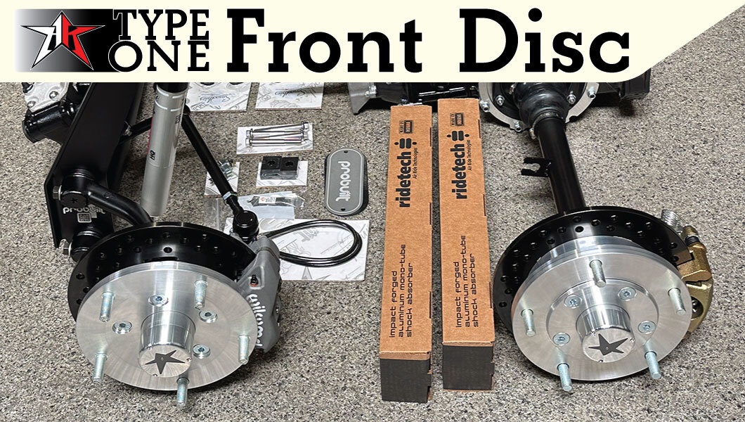
Gen 2 BAD front disc brakes with Wilwood calipers and the patented 3-piece billet BAD hub. You may have installed something like this before, but you haven't installed this one. Read the guide, understand the guide, and the install goes right the first time.
The Numbers You Need Before You Start
Watch the Install
Watch it once before you pick up a wrench. Then work through the phases below. Bedding gets its own video further down.
More on Airkewld on YouTube.
Before You Start
Five rules from the Airkewld Safety & Test Guide (AK-BR-000). They apply to every Airkewld disc brake kit with Wilwood calipers.
- Qualified installer only. Disc brakes should only be installed by someone experienced and competent with disc brakes. If you are not sure how to safely install or use this kit, do NOT install or use it.
- Do not assume anything. Verify every fitment, fastener, torque and fitting against this guide. If something does not fit or line up, STOP and call us before forcing it.
- Phone support is not an installer. Tech support from Airkewld or Wilwood can't foresee every issue on your car. You, or the person doing the install, must know how to install and use this product.
- Fluid matters. Fresh, high-performance DOT 3, DOT 4 or DOT 5.1 glycol fluid from a sealed container. Never DOT 5 silicone.
- Always test before driving. Complete the Minimum Test Procedure below before the car goes on the street. Every install, every service.
The Top 5 Install Mistakes — And How to Avoid Them
These five cause most of the calls we get. Get them right up front and the kit installs once.
01Wrong Spindle
These brakes require a DRUM-style spindle: three threaded holes around the bearing seat. Disc spindles will NOT work. Call us before you start if you are unsure.
02Cocked Bearing Race
Press races in dead straight. Even a tiny shaving in the seat causes rotor wobble. STOP if a race wants to go in uneven, then find and remove the cause.
03Greasy Seal Pocket
Tap seals in DRY. Grease in the pocket pops the seal back out. Brake-clean the area first, and grease the V-groove only AFTER the seal is seated.
04Caliper Not Parallel
Pads must contact the rotor flat, top AND bottom. Use the supplied shim assortment to center the caliper cutout before final torque to 28 ft-lbs.
05Wrong-Sequence Bleed
Disc-master sequence is RF → LF → RR → LR (NOT furthest-first). Wilwood calipers: TOP bleeder only, and yes, all of them. Top off the fluid often.
Tools Required
- Jack & Jack Stands · Front comes up on stands. Wheels go under the chassis as a failsafe.
- Oversized Channel Locks · For pulling the dust caps.
- Brake Spoon & Rubber Mallet · Back off the adjuster stars and tap the old drums off. Do not pry.
- Bearing Race Driver · Or a large socket of the right outside diameter.
- Bearing Packer & Brake Parts Cleaner · Pack the bearings. Clean every bit of grease off the spindle, seal pocket and rotor.
- 5/16″ Allen Socket · BAD hub bolt-pattern bolts · 75 ft-lbs.
- 7/32″ Allen Socket · Rotor bolts · 33 ft-lbs.
- 13mm Socket · Master cylinder firewall bolts.
- DOT 3 Fluid · Blue Loctite · Anti-Seize · Plus thread sealant for the brake light switches and a catch bottle with a hose for bleeding.
Master Cylinder — Plug the Unused Ports First
- Fits left- AND right-hand drive. The supplied master cylinder fits LHD and RHD Bugs, Ghias and Things, so it has ports on both sides. You only use one side.
- Plug the side you are NOT using. Screw in and tighten the (4) supplied 10mm pipe plugs in the unused ports, the side opposite the one you need for your brake lines and stop light switches.
- Do it on the bench, BEFORE the master goes in the car. An open or loose port leaks fluid and the system will not hold pressure.
Step by Step · The Way We'd Run It
Every phase below is from the AK-BR-001 Rev 2.1 quick reference, with the detail from our shop floor. Ball Joint and Link Pin differences are called out by part number.
Removal
- Loosen the lug nuts 1/4 turn before jacking. Raise the front and place it on jack stands. Put the wheels under the chassis as an extra failsafe.
- LHD: pull the speedo cable circlip on the driver side and save it. A piece of clear tape keeps it from falling in a crack. Stick it to your beer can.
- Pull both dust caps. Our favorite way: oversized channel locks on each edge, rock the cap up and down until it falls off.
- Save the spindle nuts and thrust washers. They get REUSED. Link Pin (4150g2): bend the lock tab over to free the nuts.
- Brake-spoon the adjuster stars to give the drum slop, then tap the edge with a rubber mallet until the drum falls off. Do NOT pry it.
- Have a container ready for fluid. Remove the bleeder on the back of the backing plate, loosen and remove the brake line, remove the (3) bolts per side and pull the backing plates.
Spindle Prep & Bracket
- Stock or drop drum spindle: wire-brush, lightly chamfer and repaint the spindle and knuckle. Steel-wool light rust off the bearing surfaces. Clean all grease and residue with brake parts cleaner.
- VERIFY a drum-style spindle: (3) threaded holes around the bearing seat. If you removed drum brakes, you have them. If they are not there, STOP and call us.
- Test-fit the inner and outer bearings BEFORE packing them. Don't fit? Call 1-623-518-3537.
- Mount the caliper bracket with the flange angled DOWN, using the supplied flathead Allens and Loctite. Torque to 35 ft-lbs in a cross pattern.
- Forged EMPI Link Pin spindles: one threaded hole is shallower. Use the supplied 20mm bolts there.
- Ball Joint kits (4151g2 / 4152g2): install the inner bearing spacer with the beveled inner edge facing the caliper plate. Link Pin (4150g2) kits skip this step.
Bearings, Races & Rotor
- Clean and chamfer as needed, then press the races home to the bottom of the seats, thin side up. A race driver works best; a large socket of the right diameter works too. Extreme force should not be needed.
- Watch the races go in straight. If one wants to go in uneven, STOP and fix the cause or replace it before continuing. A cocked race damages the hub.
- Pack the bearings with grease and place them in the rotor. Brake-clean any grease or oily residue where the seal sits.
- Tap the seal in DRY. Greased seals pop back out. Once it is seated and stays put, grease the seal V-groove so it doesn't burn off.
- Light grease on the spindle shaft and seal race area. Install the rotor with bearings, then the notched thrust washer.
- Install one lock nut (4150g2) or the clamp nut (4151g2 / 4152g2). Spin the rotor while tightening. When it stops spinning, back off 1/4 turn for end play.
- Link Pin: install the lock tab and the second lock nut, tighten, then bend the tabs over. Ball Joint: tighten the 6mm Allen clamp screw.
If a race resists going in straight, STOP. Even a tiny shaving or burr in the seat causes rotor wobble, and you will feel pulsing pads and uneven wear within a few hundred miles. Pull the race, inspect the seat with a magnifier, polish out any debris with crocus cloth, brake-clean, then reinstall. Do not force a cocked race.
Speedo Cable & Grease Caps
- Two caps come with the kit. The speedo-side cap has a square cutout on the back.
- Driver side: remove the Airkewld star with the supplied Allen wrench.
- Grease the speedo cable and slide it through the spindle until it sticks out. Rotate the dust cap until the square cutout engages.
- Slip the original c-clip onto the cable to retain it.
- Thin coat of anti-seize on the supplied stainless cap screws. Install with the provided Allen. Do NOT over-tighten. Turning a screw counterclockwise first until you hear it drop into the thread makes it start easily.
- Reinstall the Airkewld star to finish the cap, same anti-seize and same easy torque.
Caliper & Pads
- Test-fit the caliper. Use the supplied shim and washer assortment to center the caliper cutout top AND bottom so the pads contact the rotor dead flat. The caliper must sit parallel to the disc.
- Check the caliper bolts: enough thread into the bracket to hold securely, but not sticking through onto the rotor face. Too long: add a washer under the head. Too short: use a longer bolt.
- Final torque to 28 ft-lbs with Loctite.
- Lift the retainer pin assembly out, install the pads friction side toward the rotor, and reinsert the retainer pin through every hole so it locks on the locking lug.
- Porsche 356 kits: use the supplied brass-fitting adapter with your factory rubber hoses. Peel the sticker off the back of the caliper, put thread sealant on the threads and install the adapter.
Lines · Master · Bleed · Final
- Remove the old master: break the brake lines loose, disconnect the brake light wires and reservoir leads, then the (2) 13mm firewall bolts from inside near the pedals. Careful: the spacers can fall into the channel.
- Clean and PAINT the new master before install so it doesn't rust. Plug the unused ports (see above). Install the brake light switches with thread sealant, and put a small dab of grease where the pushrod contacts.
- Master spacers are REQUIRED. Verify they are there, or order them from us. Blue Loctite on the master mounting bolts.
- Port routing: rear-most port → rear brakes. Top and forward-most ports → right and left front. Lower ports → brake light switches. Tighten every fitting.
- Pushrod free play about 1/8″. Adjust at the jam nut with the rod OUT of the car; buffing the threads and adding anti-seize makes it easy. Recheck after tightening.
- Connect the reservoir, fill with fluid and leave the cap OFF while bleeding. Sequence: RF → LF → RR → LR. Top off often and never let it run dry. See Caliper Bleeding below.
- Adjust the rear shoes: brake-spoon the adjuster until the drum stops, pump the pedal 3–5 times (the drum turns again), tighten again, and repeat until the drum stays locked after pumping. Then back off until it spins free without drag. This centers the shoes and gives a better pedal.
- Install the wheels, torque the lugs and lower the car. BEFORE the first drive: press the pedal slowly to the floor and release, repeating until the pistons move into driving position and the pedal is firm at standard height. Then run the Minimum Test Procedure.
Caliper Bleeding
- Air rises. The bleeder must sit at the very TOP of the caliper or trapped air cannot escape.
- Use only the uppermost bleed screw(s). NEVER open the lower bleeders. Doing so can pull air INTO the system. Wilwood calipers are made to fit either side, so open EVERY upper bleeder, every time, even on a single-side service.
- Bleeders not on top? Remove one or both caliper mounting bolts and rotate the caliper until the bleeder points straight up.
- Block the pads. When the caliper is off the rotor, put a wood block between the pads so the pistons can't push out.
- Sequence: RF → LF → RR → LR. With a disc master you bleed the first circuit to fully bleed the second, so it is NOT furthest-first. Master cap OFF the entire bleed.
- Use a catch bottle with a hose. Never let brake fluid touch the pad or rotor contact surfaces.
Pumping it up is a symptom, not a fix. If the pedal only firms up after pumping, air is still trapped. Re-bleed, and confirm each bleeder sits at the top of its caliper before you start.
Minimum Test Procedure
From the Airkewld Safety & Test Guide (AK-BR-000). Five phases. Do not skip one.
1Pedal Check · Stationary
- Seat the pistons: press the pedal slowly to the floor and release. Repeat until the pedal is firm at standard height.
- Hold firm pressure for several minutes. It must stay put WITHOUT sinking.
- Pedal sinks toward the floor? Check the system for leaks.
- DO NOT drive if the pedal won't stay firm or can be pushed to the floor with normal pressure.
2Creep Test · 2–5 mph
- At very low speed, apply the brakes HARD several times while turning the steering from full left to full right.
- Repeat several times.
- Remove the wheels and confirm nothing is touching, rubbing or leaking.
3Inspect
- Examine every brake component, line and fitting for leaks and interference.
- Confirm NO interference with the wheels or suspension.
- Confirm the bleeders are closed and the caliper bolts are at final torque.
4Low-Speed Stops · 15–20 mph
- Make moderate and hard stops at low speed.
- Brakes should feel normal and positive: no pull, grab, pulsing or noise.
- Stop and check again for leaks and interference before going any faster.
5Bed-In
- Bed the pads and rotors before any hard driving. Full procedure and video below.
Always test somewhere with no danger to or from other people or vehicles, like an empty lot, not your street. Wear your seat belt and use all of the vehicle's safety equipment. Have a second person watch the wheels during the creep test.
Pad & Rotor Bedding
- 8–10 LIGHT stops from about 30 mph down to 15 mph, with 20–30 seconds to cool between each.
- 8–10 MODERATE stops from about 45 mph down to 30 mph, same 20–30 second cool-down.
- 8–10 HARD stops from 55–65 mph down to 25 mph, same cool-down between each.
- Cruise at a moderate speed with as little brake contact as possible until most of the heat is gone. Do NOT sit at a stoplight with the pedal pressed.
- Park and let the brakes cool to ambient air temperature.
Watch the bed-in before your first drive.
Only bed the brakes after the system has passed the Minimum Test Procedure, and only on a track or another safe place where you can legally reach 65 mph and slow down hard.
Why We Bed
Bedding is a real-conditions heat cycle and the last step in preparing new pads and rotors. Bringing cast iron rotors up to temperature gradually and letting them cool slowly relieves stress left from casting and machining, lays down an even layer of pad material on the rotor face, and finishes curing the pads. Skip it and you get glazed pads, warped rotors and a pulsing pedal.
Wilwood's Bedding Notes
- On-and-off technique. Apply the brakes for 3–5 seconds, then fully release for about twice as long (5 count on, 10 count off) so the heat soaks into the pads and rotors.
- Fade means stop. If you notice any brake fade during the cycle, start the cool-down drive immediately.
- A firmer feel should develop as you go. That is the bedding working.
- Post-bedding check: the rotors should show a uniform burnished finish across the whole contact face. Smearing or splotches mean the brakes were heated too fast. If it does not blend away on the next cycle, or the brakes chatter, the rotors need sanding or resurfacing.
- Keep fluid off the friction surfaces. Never let brake fluid contaminate the pads or rotors. Use a catch bottle with a hose when bleeding.
Swaps, Studs & Replacement Parts
BAD Hub Bolt-Pattern Swap
The patented 3-piece BAD (Billet Assembled Disc) hub swaps bolt patterns in about 20 minutes per side. 5/16″ Allen socket, blue Loctite, 75 ft-lbs. Crack the bolts loose with a breaker bar and a lever between the studs. An impact WILL strip the socket or break the bolt.
Rotor Replacement
7/32″ Allen socket, blue Loctite, 33 ft-lbs. Same rule: breaker bar and a lever between the studs, never an impact.
Lug Nuts & Studs
Kits ship with 14mm x 1.50 studs; 12mm x 1.50 can be special ordered. Every wheel needs its own lug seat (60° taper, ball or mag), so have the right nuts on hand. Studs can be trimmed to length with a cut-off tool.
Porsche 356
A late-model 914 master cylinder is needed with these brakes. The kit includes a brass-fitting adapter for your factory rubber hoses.
| Kit | Inner Seal | Inner Bearing | Outer Bearing |
|---|---|---|---|
| 4150g2 · Link Pin | 111405641B | 111405627 | 111405647 |
| 4151g2 · Ball Joint, stock spindles | 131405641A | 311405625 | 311405625 |
| 4152g2 · Ball Joint, drop spindles | 111405641B | 311405625B | 311405645 |
Maintenance & Warranty
Maintenance
- Brakes must be checked regularly for fatigue, damage and wear.
- Inspect pads, rotors, calipers, hoses and fittings at every service. Racing / off-road: inspect the calipers after EVERY use.
- Brake fluid absorbs moisture. Flush with fresh fluid on a regular schedule and after any track use.
Warranty & Responsibility
Calipers are manufactured by Wilwood Engineering, Inc., Camarillo, CA, and are sold subject to Wilwood's Disclaimer of Warranty. Performance brake components are used under widely varying conditions that the manufacturer and seller cannot control. Selecting, installing, testing and maintaining the system, and deciding whether it is suitable for your application, is the responsibility of the purchaser and installer. Full Wilwood terms: wilwood.com · (805) 388-1188.
The Questions We Get Most
My pedal is spongy, but it gets firm if I pump it. Is that OK?
No. Pumping it up is a symptom, not a fix. Air is still trapped. Re-bleed using the TOP bleeder on every Wilwood caliper, in the RF → LF → RR → LR order, with the bleeders pointing straight up.
Will these fit my disc spindles?
No. These brakes need a stock or drop DRUM spindle with three threaded holes around the bearing seat. If you are not sure what you have, call us before you start.
Which brake fluid should I use?
Fresh, high-performance DOT 3, DOT 4 or DOT 5.1 glycol fluid from a sealed container. Never DOT 5 silicone in these calipers.
Why not bleed the furthest wheel first?
With a disc brake master like the one supplied, you need to bleed the first circuit to fully bleed the second. Start right front, then left front, right rear, left rear.
What do I do with the extra ports on the master cylinder?
The master fits left- and right-hand drive cars, so it has ports on both sides. Plug the side you are not using with the (4) supplied 10mm pipe plugs, on the bench, before the master goes in the car.
Do I really need to bed the brakes?
Yes. Skipping it glazes the pads and can warp new rotors. Run the bedding cycle after the Minimum Test Procedure and before any hard driving.
Do I need to adjust my rear drums?
Yes. Properly adjusted rear shoes give a noticeably better pedal on a front-disc conversion. Follow the shoe-centering steps in Phase 6.
More Brake Guides & Kits
Real Humans. Real Phones. Real VW People.
If something doesn't fit or line up, stop and reach out before you force it. Have your order number and photos ready.